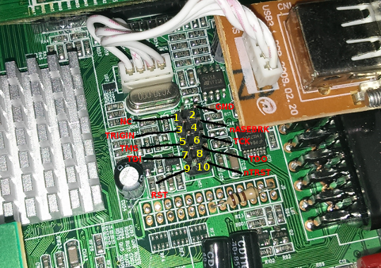
# Types of JTAG headers per device family For target mechanical requirements that could impact device heights in proximity to the emulation header on your board and possible keep-out areas required for good connection and room to disconnect the cable connector, see your XDS manufacturer's documentation. Target cable design and connectors vary between XDS manufacturers. For part numbers, check the next section. For part numbers, check the next section.ģ0.05" (1.27mm) pin and row pitch. For part numbers, check the next section.Ģ0.05" (1.27mm) pin pitch, 0.10" (2.54mm) row pitch. * For ARM connectors, see ()ġ0.10" (2.54mm) pin and row pitch. * For MSP430 see (./files/JTAG_MSP430_legacy.pdf) for details. * For the TI 60 pin connector and the MIPI 60 pin connector, please check the (). * Part numbers for connectors and headers are at the bottom of the table and at section (#connector-information). * For Trace, you may also want to consider reading ()


* The document () describes the 14-pin JTAG connector and target board electrical requirements for XDS510 JTAG support (despite it's title it is not specific to the TMS320C6000 DSP). This page covers in detail several aspects to properly identify, specify and use these different standards. Texas Instruments supports a variety of JTAG connection methods to both its development kits and custom boards.


 0 kommentar(er)
